


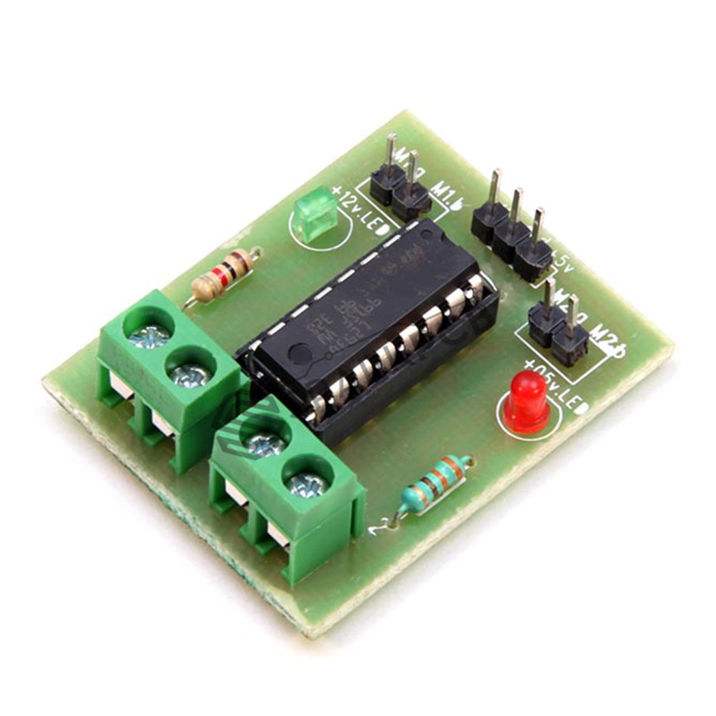
L293D Motor Driver Shield
109.00
The L293 and L293D devices are quadruple high-current half-H drivers. The L293 is designed to provide bidirectional drive currents of up to 1 A at voltages from 4.5 V to 36 V. The L293D is designed to provide bidirectional drive currents of up to 600-mA at voltages from 4.5 V to 36 V. Both devices are designed to drive inductive loads such as relays, solenoids, DC and bipolar stepping motors, as well other high-current/high-voltage loads in positive-supply applications.
Each output is a complete totem-pole drive circuit, with a Darlington transistor sink and a pseudo- Darlington source. Drivers are enabled in pairs, with drivers 1 and 2 enabled by 1,2EN and drivers 3 and 4 enabled by 3,4EN. The L293 and L293D are characterized for operation from 0°C to 70°C.
FEATURES:
• Wide Supply-Voltage Range: 4.5 V to 36 V
• Separate Input-Logic Supply
• Internal ESD Protection
• High-Noise-Immunity Inputs
• Output Current 1 A Per Channel (600 mA for L293D)
• Peak Output Current 2 A Per Channel (1.2 A for L293D)
• Output Clamp Diodes for Inductive Transient Suppression (L293D)
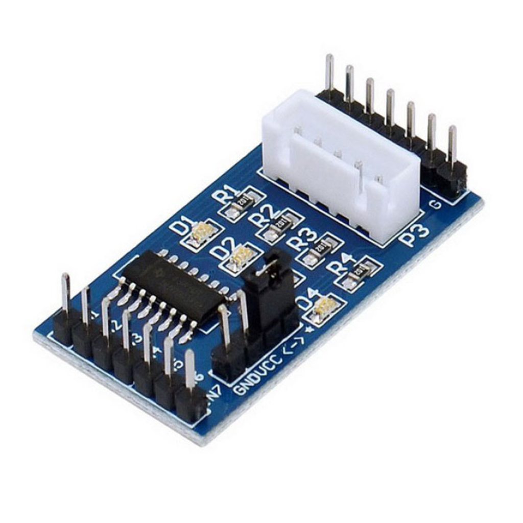
Stepper motor with Driver Board
199.00
The ULN2003 stepper motor driver PCB provides a direct drive interface between your microcontroller and stepper motor. The PCB provides 4 inputs for connection to your microcontroller, power supply connection for the stepper motor voltage, and ON/OFF jumper, a direct connect stepper motor header and 4 LEDs to indicate stepping state.
Stepper Motor Connection:
Connect stepper motor to this header. If you use one of our stepper motors they will just plug directly into the header. If you have another brand without the correct header plug, you could solder the wires directly to the back of the PCB.
Step State LEDs:
Indicate which channel is active.
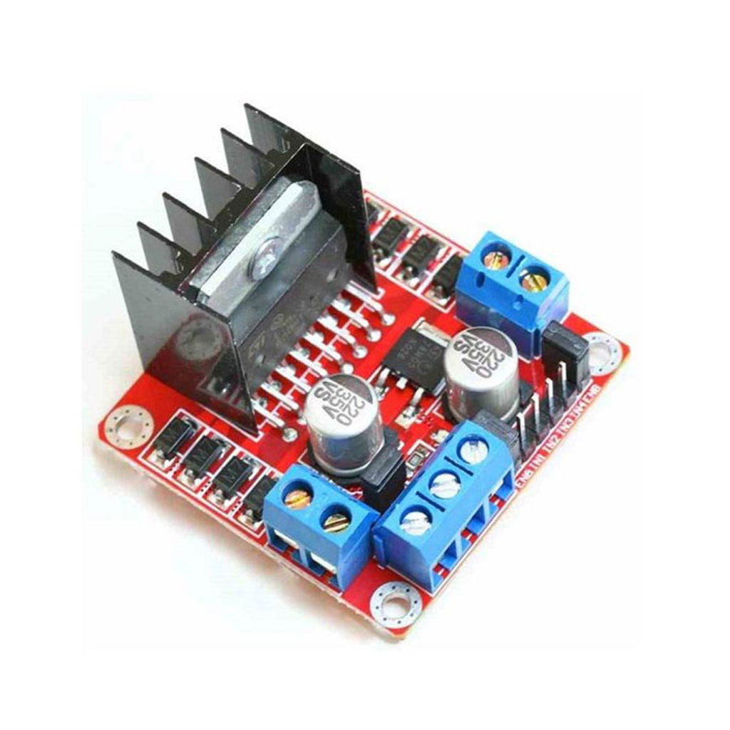
L298P Motor Driver Shield
249.00
The L298 Driver is a high voltage, high current dual full bridge driver designed to accept standard TTL logic levels and drive inductive loads such relays, solenoids, DC and stepping motors. Two enable inputs are provided to enable or disable the device independently of the input signals. The emitters of the lower transistors of each bridge are connected together the corresponding external terminal can be used for the connection of an external sensing resistor.
Features:
- Operating supply voltage up to 46 V
- Total DC current up to 4 A
- Low saturation voltage
- Over temperature protection
- Logical "0" input voltage upto1.5 V (HIGH NOISE IMMUNITY)
- Two motor direction indicator LEDs
- An onboard user-accessible 5V low-dropout regulator
- Schottky EMF-protection diodes
- Screw-terminals for power and motor connections
- High quality PCB FR4 Grade with FPT Certified